 TECNOLOGÍAS
para un mundo mejor
TECNOLOGÍAS
para un mundo mejor
Escornabot
Como construir un Brivoi audacius?
http://escornabot.org/wiki/index.php?title=P%C3%A1gina_principal
Si estás leyendo esto debe ser porque estás interesado en construir nuestra versión totalmente DIY del Escornabot... ¡Una elección valiente! El Brivoi Audacius se construye con drivers independientes para los motores, conectando tu Arduino en una breadboard y tienes que hacer tu propia botonera en una stripboard. Ciertamente, esto puede ser un poco más lioso que montar el Brivoi compactus, pero a cambio también aprenderás más y... aquí estamos para ayudar :)
Estos son, en esencia, los pasos que debes seguir:
Lee la lista de material (Bill Of Materials, BOM) y encarga las cosas que necesites.
Monta y suelda la botonera.
Monta el chasis y el cableado.
Configura y carga el firmware.
Pincha en los enlaces de abajo si quieres comenzar una aventura robótica! :)
BOM Brivoi Audacius
Audacius Keypad
Check and configure keypad readings
Mount chassis
Wire connections
Upload Code
https://escornabot.com/web/en/content/howto-audacius
1º BOM Brivoi Audacius
As on every current version, you must get some printed parts and some non printed parts to build your Brivoi audacius. If you are familiar with electronics and microcontrollers, you may change some of the things we use, maybe you even find a better option! If so, don't forget to tell us on the mailing list... we're an Open Source Project!
WARNING Currently, we do not sell or have any commercial agreement with anybody, every link posted aims only to help you find the items, we do not recommend or guarantee any of the listed shops.
For the escornabot
| Thing | How many? |
|---|---|
| 5V 28BYJ-48 Stepper Motors with their ULN2003 drivers | 2 |
| Arduino Nano or similar | 1 |
| 170 pts Breadboard | 1 |
| 5V Active Buzzer | 1 |
| 14 mm diameter ball (steel or other) | 1 |
| 2x2 R-6 AA battery holder | 1 |
| 63x3 mm rubber O-rings | 2 |
| Male-Female jumper wires | 15 units |
| Slide switch 19x6 mm (optional) | 1 |
| 10 mm. M3 screws | 16 |
| M3 nuts | 2 |
| 0.28 mm2 solid wire | 10 cm |
Keypad:
| Component | Quantity |
|---|---|
| 18X17 lines Stripboard | 1 |
| 6x6 mm SPST-NO tact switch | 5 |
| 10KΩ Resistors (1/4 watt) | 6 |
| 1MΩ Resistors (1/4 watt) | 1 |
| 0.28 mm2 solid wire | 1 |
| 2.54 Right angle connector (or any other header pin of your choice) | 1 |
| Male Header pins (optional) | 2 |
| Jumper Cap (optional) | 1 |
Printed Parts (these should change in a bit)
| Printed Parts | How many? |
|---|---|
| BallCaster_14.5mm.stl | 1 |
| Addon-BoardBracket.stl | 1 |
| BatteryBracket.stl | 1 |
| Addon-KeypadBracket.stl | 1 |
| MotorBracket.stl | 1 |
| WheelNG.stl | 2 |
| Addon-SwitchHolder.stl (optional) | 2 |
How much does this cost?
Well... it depends! We think it can get really cheap, but it will depend on where you buy the components and on if you have a 3D printer on your own or you have to buy the printed parts. Anyway, it's a highly affordable robot, as it should be! :)
2º Audacius Keypad
So, as we told you before, to be a true audacius robot-maker, you will have to mount and solder your own keypad. We will explain how to do it as detailed as possible, assuming no familiarity with this kind of things. If you have some basic electronics and soldering skills, we guess that taking a look at the schematics will be enough for you.
So... let's get started!
Is it the first time you will solder?
Even if you have never soldered before, this is not so difficult. It is just putting a drop of solder in each hole that a component is placed, making sure they get a electrical connection with the board and that they also get a mechanical connection that avoids them from falling. We recommend you to take a look at this fantastic comic, it will take you 15 minutes and you will know everything you need to know.
Check stuff
This is what you should have in your desk to start with the keypad:
| Component | Quantity |
|---|---|
| 18X17 lines Stripboard | 1 |
| 6x6 mm SPST-NO tact switch | 5 |
| 10KΩ Resistors (1/4 watt) | 6 |
| 1MΩ Resistors (1/4 watt) | 1 |
| 0.28 mm2 solid wire | 1 |
| 2.54 Right Angle connector (or any other header pin of your choice) | 1 |
| Male Header pins (optional) | 2 |
| Jumper Cap (optional) | 1 |
Cut the stripboard
You probably won't find a stripboard that is precisely the size we ask for. It's not a problem, you just have to cut it, and it's very easy!
We recommend you to see this video , put some gloves on, and proceed!
Cut the lines on a stripboard
With some sharp knife or xacto, you have to make two cuts on the lines of the stripboard. Very carefully, you have to strip off a bit of the copper on the places marked in red, so that there is no electric connection between the holes on the sides.

Drill holes
Take a drill with a 3 mm. bit and make four holes, exactly over the stripboard's holes that we mark in green.

Place components
The placement is fully explained on the wiki. Switches stay in place quite well, but resistors and wires tend to fall when you turn the board down, you should bend their terminals forming an
angle so they don't sweep through the holes so easily. This is the final placement of every component.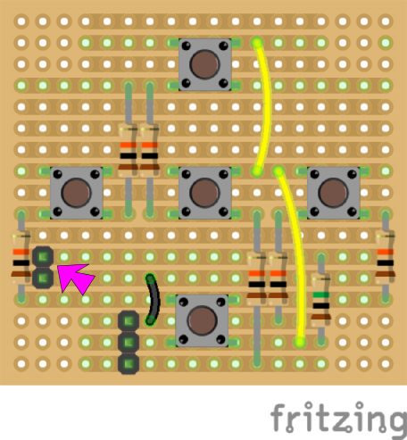
NOTE: Do you see the two black squares pointed with a pink arrow? Those are the two optional header pins that we told you. You only need to put them in case you want to work with 3-wire configuration on your keypad. Escornabot's firmware comes set by default to a two-wire keypad, so, if you are not sure what to do, just don't put this component.
Solder components
Well... you've read THE COMIC, haven't you? So, you know how to do it... Go! :)
3º Check and configure keypad readings
If your escornabot doesn't work right away after you've uploaded the code and connected the keypad, you should check the values that the Arduino is reading. As you've seen, the keypad consists of a bunch of resistors and buttons connected to the Arduino. Depending on the button you press, more or less resistors will get in the way of the current, and the analog pin will read a different voltage.
2-Wire Keypad (standard)
Connection
We are going to connect the keypad to the Arduino, as shown below:
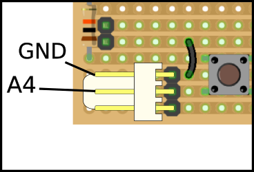
As you can see, bottom pin of the connector remains unused, central pin goes to Arduino's A4 pin and top pin goes to Arduino's GND.
Reading the readings
Open Arduino IDE, copy & paste this sketch and upload it.
 #define KEYBOARD_PIN A4
    #define KEYBOARD_WIRES 2 // change to 3 in old buttonsets with 3 wires

    void setup() {
      pinMode(KEYBOARD_PIN, KEYBOARD_WIRES == 2 ? INPUT_PULLUP : INPUT);
      Serial.begin(9600);
    }

    void loop() {
      Serial.println(analogRead(KEYBOARD_PIN));
      delay(200);
    }
Can you see the magnifying glass on the top right corner of the Arduino IDE? If you press it, a window should open showing numbers close to 1024. Every time you push a button, this number should change. Write down the values of each button pressed, each value will be assigned to a particular behaviour of the escornabot.
Modifying escornabot's firmware
Now that you know the values that your keypad gives, we have to put them on our firmware so that the escornabot acts accordingly to each button pressed. We assume you have downloaded the code, open it and look for the folllowing lines in the Configuration.h tab:
 // input values for each key pressed
    #define BS_ANALOG_VALUE_UP 471
    #define BS_ANALOG_VALUE_RIGHT 299
    #define BS_ANALOG_VALUE_DOWN 211
    #define BS_ANALOG_VALUE_LEFT 118
    #define BS_ANALOG_VALUE_GO 158
    #define BS_ANALOG_VALUE_RESET 82
Those are the values that come set by default, so, if they are different to the values you have previously written down, you must change them. For example, if you read 167 when pressing "GO" button, you must put that number instead of "158".
As you can see, firmware is ready for a six button keypad, but you only have 5. You must put BS_ANALOG_VALUE_RESET to "0", as long as you don't have that button.
Now, your escornabot should follow your orders right away!
Three-wire Keypad (Custom)
--ToDo--
4ºMount chassis
We believe we can't do better than this to show you how easy is to mount Audacius chassis. Pictures are self-explanatory, but you can even learn some spanish for the same price! ;)
http://escornabot.org/wiki/index.php?title=Gu%C3%ADa_de_montaje_(Brivoi)
5º Wire connections
It's very easy to wire your escornabot, you just need some (14-15) male-female jumpers and follow this simple steps.
Plug motors to drivers:
Easy! they only go in the proper way and then... well, left motor to left driver, right motor to right driver! Did you expect that?
Plug the arduino on the breadboard
Carefully or not, stick the arduino on the breadboard. Be sure to leave three empty rows of the breadboard on the same side as in the picture. From now on, you can reach any pin in the arduino just sticking the "male" side of the jumper on the same column as the pin. For example, that orange wire of the picture would connect whatever to arduino's D6 pin.

Plug drivers to arduino.
Usually, drivers have four pins labelled IN1 to IN4, and two separate pins labelled "+" and "-".

You need 12 male-female jumpers to connect each driver pin to one of the rows of the breadboard with the arduino. Watch picture and just follow the table!
| Left Driver | Arduino | Right Driver | Arduino |
|---|---|---|---|
| IN1 | D9 | IN1 | D5 |
| IN2 | D8 | IN2 | D4 |
| IN3 | D7 | IN3 | D3 |
| IN4 | D6 | IN4 | D2 |
| - | GND | - | GND |
| + | VIN | + | VIN |
Plug keypad
We showed you before, if you're using a two-wire keypad (default), you just need to connect the upper pin with GND on the Arduino and the middle pin to A4. If you're using a three-wire keypad (custom geeky configuration) you also have to connect the bottom pin to 5V. Watch picture!

Plug buzzer
Unfortunately, if you're using an Arduino Nano, the buzzer is not going to fit properly on the breadboard. Of course, you are thinking that we are not very good designers. You are right, but, of course, we've got an excuse! (1).
Anyway, it's not very elegant, but we've got a workaround. You have to solder to pieces of solid core wire on both legs of the buzzer, then plug the long leg, also labeled "+" to the D10 pin and the short leg to GND. We hope you see what we mean with this two beautiful pictures!

Feed it!
Now, we need to supply our escornabot the energy it deserves... so take the red wire that comes from the battery and plug it on the Vin line of the arduino, and take the black wire to GND. It's quite nice to put some kind of male terminal on this wires.
So, you're done with this... you only have to download the code to your computer and upload it to the arduino!
(1) - We started using Arduino Pro Mini, it's a bit smaller than Nano, so the buzzer fit. Pro Mini doesn't have USB connection, so you have to buy an special connector to program it. That is the reason why we switched the default controller to Arduino Nano, although now you have to make this akward operation to connect it.